The Fiscal Year 2024 Awards list can be viewed here. There you can find a concise summary of our proposed project:
“Radio frequency systems used to heat plasmas in fusion power plants will need to be highly efficient and adaptable to changes in the plasma over time. This proposal is for the scaling of an innovative radiofrequency amplifier which produces less heat waste and can follow the changes in the plasma.”
This work leverages our prior experience with and development of high-efficiency radiofrequency amplifiers under our ARPA-E GAMOW contract. The scaling towards application in a plasma fusion reactor would require power-combining of 10’s-100’s of RF boards. The RF amplifiers utilize a Reactance Steering Network (RSN) developed by our collaborators at Princeton University to handle variations in the impedance of a load, which in our case is a plasma. Experiment testing and simulation will be performed to assess the power-combining of multiple RSNs so that we can scale up to high-power operation on the scale of 0.1 – 1 MegaWatts, that is, 100,000-1,000,000 Watts!
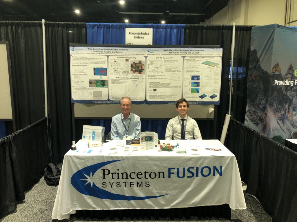
At the end of March, we attended the ARPA-E Energy Innovation Summit in National Harbor, MD. At the Summit we presented our work on power electronics tailored for fusion systems under an ARPA-E GAMOW grant. It was a great experience to network with many other awardees of ARPA-E grants working on innovative energy projects and learn about the power electronics needs of potential customers so we could design our boards to these specifications. Shown below is our Summit booth which was run by PFS Mike Paluszek and me.
Breakout sessions included panels on: future plans for inertial fusion energy, nuclear & materials, rethinking the nuclear waste challenge, and scaling up innovations for impact in the private sector with the ARPA-E SCALEUP program. Dr. Neil deGrasse Tyson gave a talk at the Summit!
The pdfs of the trifold and posters at our Summit booth are shown below. If you have any power electronics requirements for your systems, please contact us at info@princetonfusionsystems.com!
The Fusion Energy Toolbox for MATLAB is a toolbox for designing fusion reactors and for studying plasma physics. It includes a wide variety of physics and engineering tools. The latest addition to this toolbox is a new function for designing tokamaks, based on the paper in reference [1]. Tokamaks have been the leading magnetic confinement devices investigated in the pursuit of fusion net energy gain. Well-known tokamaks that either have ongoing experiments or are under development include JET, ITER, DIII-D, KSTAR, EAST, and Commonwealth Fusion Systems’ SPARC. The new capability of our toolboxes to conduct trade studies on tokamaks allows our customers to take part in this exciting field of fusion reactor design and development.
The Fusion Reactor Design function checks that the reactor satisfies key operational constraints for tokamaks. These operational constraints result from the plasma physics of the fusion reactor, where there are requirements for the plasma to remain stable (e.g., not crash into the walls) and to maintain enough electric current to help sustain itself. The tunable parameters include: the plasma minor radius ‘a’ (see figure below), the H-mode enhancement factor ‘H’, the maximum magnetic field at the coils ‘B_max’, the electric power output of the reactor ‘P_E’, and the neutron wall loading ‘P_W’, which are all essential variables to tokamak design and operation. H-mode is the high confinement mode used in many machines.
Illustration of the toroidal plasma of a tokamak. R is the major radius while a is the minor radius of the plasma. The red line represents a magnetic field line which helically winds along the torus. Image from [2].
This function captures all figure and table results in the original paper. We implemented a numerical solver which allows the user to choose a variable over which to perform a parameter sweep. A ‘mode’ option has been incorporated which allows one to select a desired parameter sweep variable (‘a’, ‘H’, ‘B_max’, ‘P_E’, or ‘P_W’) when calling the function. Some example outputs of the function are described below.
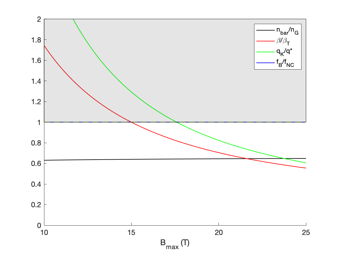
As an example, we will consider the case of tuning the maximum magnetic field at the coils ‘B_max’. The figure below plots the normalized operation constraint parameters for a tokamak as functions of B_max from 10 Tesla to 25 Tesla. The unshaded region, where the vertical axis is below the value of 1, is the region where operational constraints are met. We see that for magnetic fields below about 17.5 Tesla there is at least one operation constraint that is not met, while for higher magnetic fields all operation constraints are satisfied, thus meeting the conditions for successful operation. This high magnetic field approach is the design approach of Commonwealth Fusion Systems for the reactor they are developing [3].
Operational constraint curves as a function of B_max. Successful operation occurs if all of the curves are in the unshaded region. Note, f_B/f_NC, a ratio of the achievable to required bootstrap current, is set equal to 1. In this case P_E = 1000 MW, P_W = 4 MW/m2, and H = 1. For more details on the plotted parameters and how they function as operational plasma constraints, see reference [1].
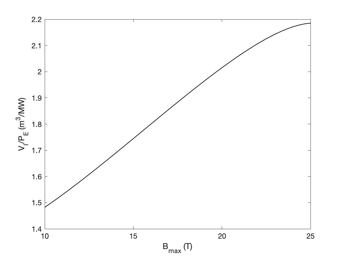
Note, however, that there is a material cost associated with achieving higher magnetic fields, as described in reference [1]. This is illustrated in the figure below, which plots the cost parameter (the ratio of engineering components volume V_I to electric power output P_E) against B_max. There is a considerable increase in cost at high magnetic fields due to the need to add material volume that can structurally handle the higher current loads required.
Cost parameter (units of volume in cubic meters per megawatt of power, m3/MW) as a function of B_max.
In this post we illustrated the case of a tunable maximum magnetic field at the coils, though as mentioned earlier, there are other parameters you can tune. This function is part of release 2022.1 of the Fusion Energy Toolbox. Contact us at info@psatellite.com or call us at +01 609 276-9606 for more information.
Thank you to interns Emma Suh and Paige Cromley for their contributions to the development of this function.