Historical data from the PFRC-2 experiment at Princeton Plasma Physics Laboratory is now available online as part of Princeton University’s Data Commons!
https://datacommons.princeton.edu/discovery/catalog/doi-10-34770-8ecv-zm19
The data includes Excel, HDF5, TXT, TRC and MCA files for the experiments conducted using PFRC between 2014 and 2023. The data is organized as one tarball per experiment day. If a particular day’s experiment is referenced in a paper, interested readers can now easily grab that day’s data! PPPL maintains a list of pertinent papers at this page:
https://w3.pppl.gov/ppst/pages/pfrc_papers.html
According to the description of the data:
Data includes raw, intermediate and post processed data from the interferometer, fast camera, visible spectroscopy and SDD X-ray diagnostics, RF power characteristics, pressure gauges, probes, gas puff characteristics, axial boundary potentials, and residual gas analyzer (RGA). There is a lot of data in these files that are PDF documents made by scanning screenshots of Lecroy Digital Storage Oscilloscopes displays used to accumulate and analyze the data, Runsheet based on the diagnostics that displays the experimental parameters and the file numbers.
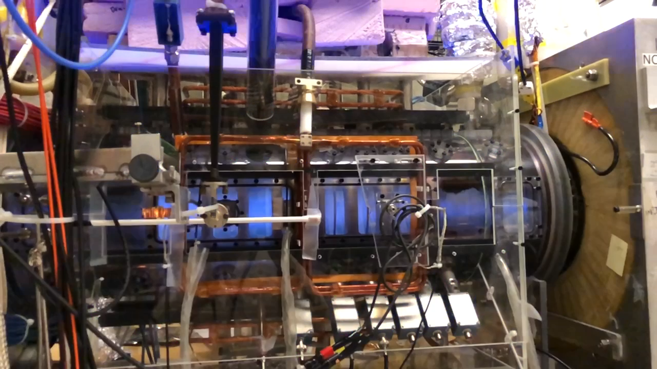
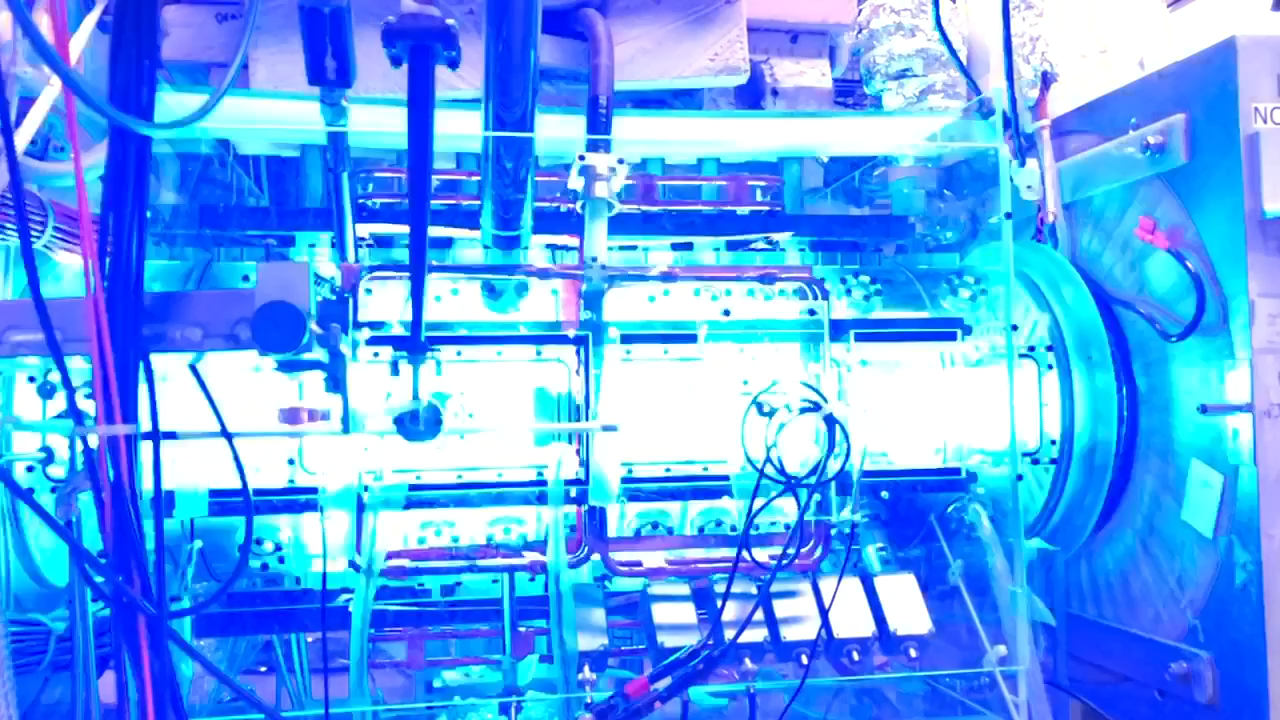
Data from the Princeton Field Reversal Configuration (PFRC) Experiment
The figure below shows one example of the oscilloscope screenshots, from the data README file.
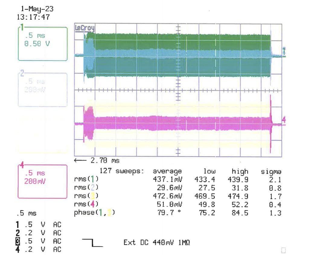
PDF of Lecroy DSO showing forward and reverse RMF powers for the two antenna sets. Top: N/S antenna set. Bottom T/B antenna set. Bottom table– values averaged over 127 discharges. Example for N/S forward power. N/SPRMF = 430*V2 kW/2 =0.4372 430/2 = 41 kW. The reflected N/S power is a small fraction of the forward power, (29.6/437.1)2 = 0.46%
The data from the PFRC-2 has been taken at the following RMFo frequencies:
| Approximate RMF frequency (MHz) | Start date | End date |
|---|---|---|
| 8.0 | 01-01-2011 | 05-13-2019 |
| 6.0 | 05-20-2019 | 11-11-2019 |
| 4.3 | 12-05-2019 | 11-01-2022 |
| 1.8 | 11-05-2022 | — |
We hope that the data repository allows more researchers to explore the PFRC-2 data!